Regeneration Tower
The heart of the liquid nitrogen generator is the regeneration tower. Within the tower pressurized, warm gas is gradually cooled until it expands at the throttle. When the gas temperature drops sufficiently at the throttle some of it liquefies. The remainder of the cold, expanded gas recirculates around the tubing to affect the cooling process. In other words, the tower regenerates the "cold" for further cooling by using the waste gas.
The tower is 50 inches high by 24 inches in diameter. The body is made from a concrete form tube. Earlier iterations used a large recycle container. I felt a longer run of tubing would allow a more rapid temperature drop, so I needed more room for the coils. The coils are made from 80 feet of 1/4 inch OD 304 seamless stainless steel tubing with a 0.035 inch wall thickness. An additional 10 feet of tubing connects to the main 80 foot coil and the reservoir. This allows one to easily disconnect and service the container and valve.
Gas circulates around the tubing, using a counter-current method to cool the pressurized stream. This maintains the greatest temperature gradient throughout the run of the tubing. When the gas expands it cools down. The cold gas recirculates over the tubing cooling it even further. During the next expansion cycle the released gas achieves an even colder temperature. This cycle eventually cools the gas to cryogenic temperatures.
The big problem is keeping the surrounding room temperature away from the cold tubing. Small heat leaks will slow or even prevent one from obtaining a sufficient temperature drop. Commercial systems have the tubing contained in a giant vacuum tower filled with vermiculite. This is beyond my price range. I used industrial alumina silica wool. When lightly packed, the wool and air make an excellent thermal shield. I wrapped the tubing with HVAC polypropylene tubing as an added barrier.
The gas used for cooling the tubing has cryogenic temperatures which will causes standard materials to fail. Initially, I got coaxial plastic tubing and wrapped this around the steel tubing. At low enough temperatures the tubing would crack. I decided to use PTFE (Teflon) tubing (1" corrugated tubing) to contain the counter-current cooling gas because it can withstand these temperatures. Since the steel tubing came in 20 foot sections, I had to make sure there was enough space for airflow. Ideally, one 80 foot run of tubing should be used. The Teflon is very expensive so I got it made in China. I only used 60 feet of Teflon to contain the cost. The remaining 20 feet uses plastic tubing because at this point the gas temperature is close to the ambient temperature, and the plastic will not suffer thermal failure.
I was able to get more rapid cooling by adding a turbinator. Normally, the gas flows over the tubing as a smooth laminar stream. Only a fraction of the gas makes contact with the steel surface, reducing thermal transfer. By wrapping a thin copper coil around the tubing one can cause air turbulance. This allows all of the gas to make contact with the tubing, increasing thermal transfer.
Below are images showing the original concept and the progression to the final tower configuration:
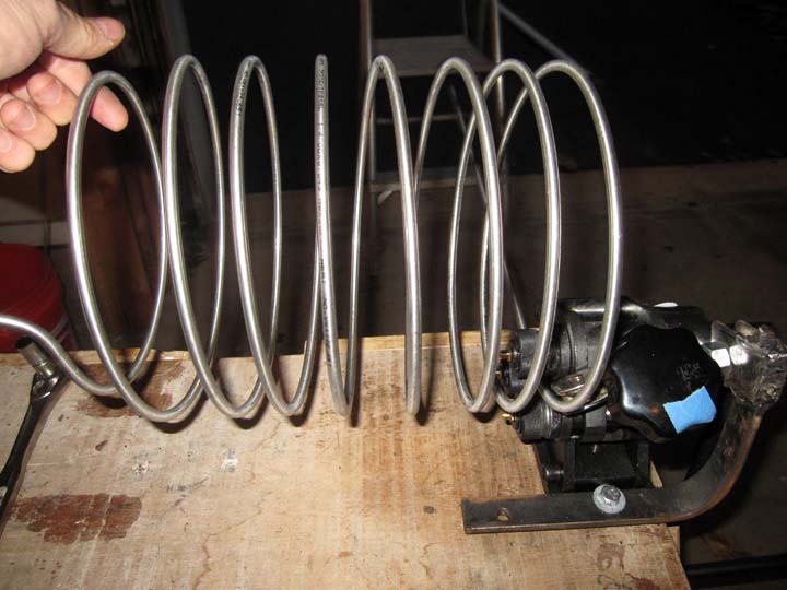
Coiling the tubing
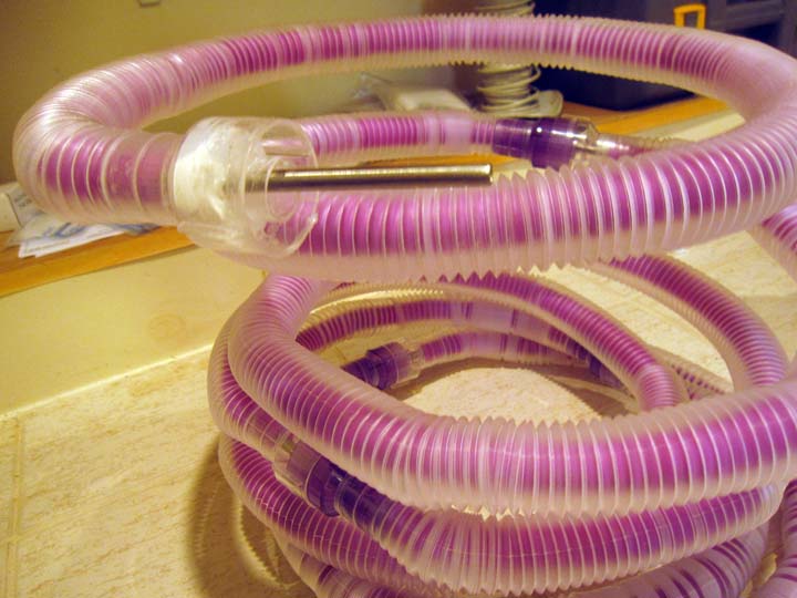 Simple plastic coaxial tubing over steel tubing. This failed at cyrogenic temperatures.
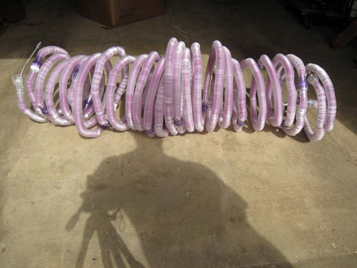 Full run of tubing for countercurrent system.
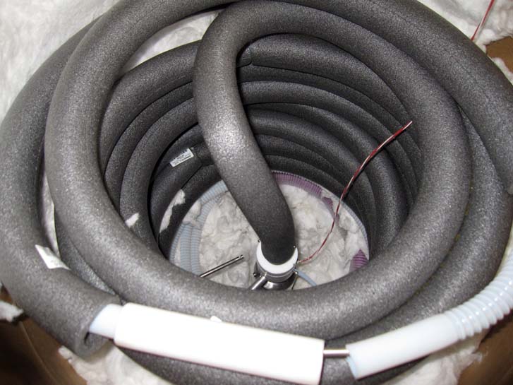
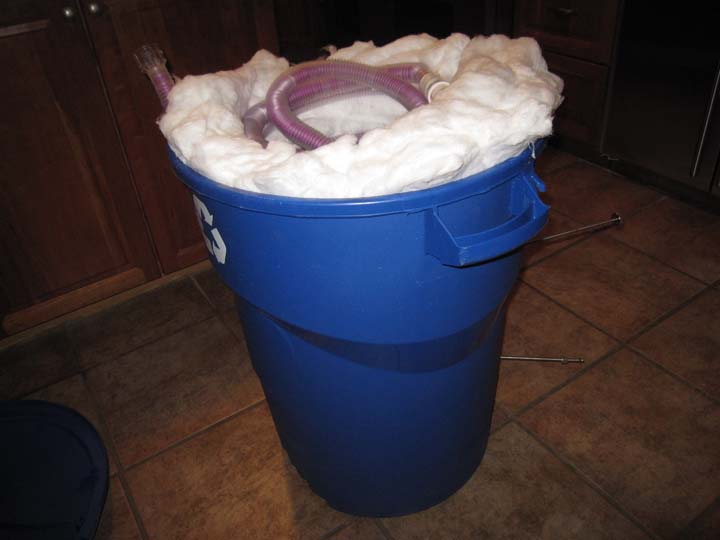 Original design using 36 gallon recycle can. Sixty feet of tubing is used. Insulation is alumina silica wool. This did reach cyrogenic temperatures as long as the plastic tubing did not fail.
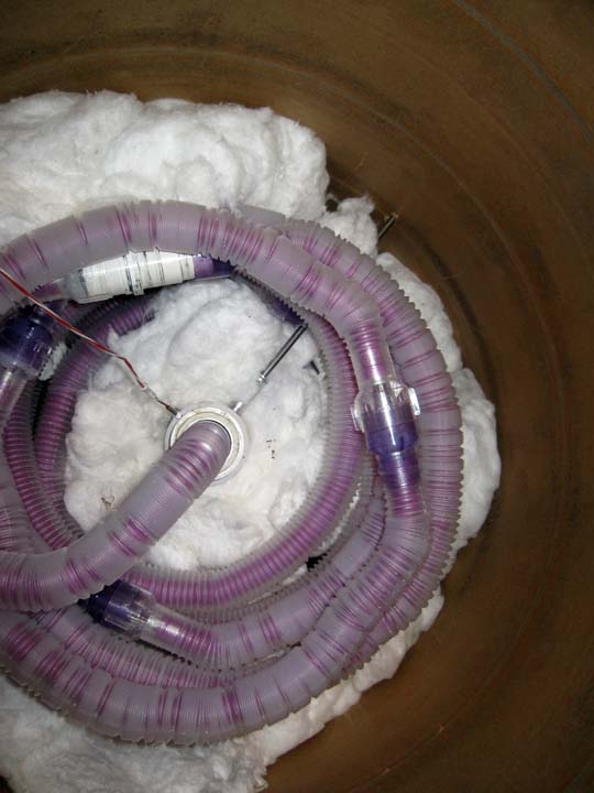
Top view of partially filled container. This version used a concrete form tube.
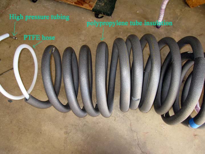
Improved design that withstands cyrogenic temperatures. PTFE is used for countercurrent hose. Polypropylene shell insulates along with alumina silica wool.
Top view with container partially filled with insulation. Lower 20 feet uses standard plastic tubing to save money as this does not see cyrogenic temperatures. Teflon connector is used to connect final 10 foot run of tubing/Teflon hose. Then, the entire inside is filled with insulation. Total length is 90 feet of 1/4" 305 seamless stainless steel 0.035" wall.
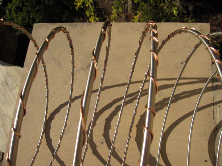
Thin square copper wire is wrapped around the tubing to break the laminar flow of gas. This turbulent flow prevents a warmer layer of gas hugging the tubing and is more efficient for the thermal transfer of heat out of the tubing.
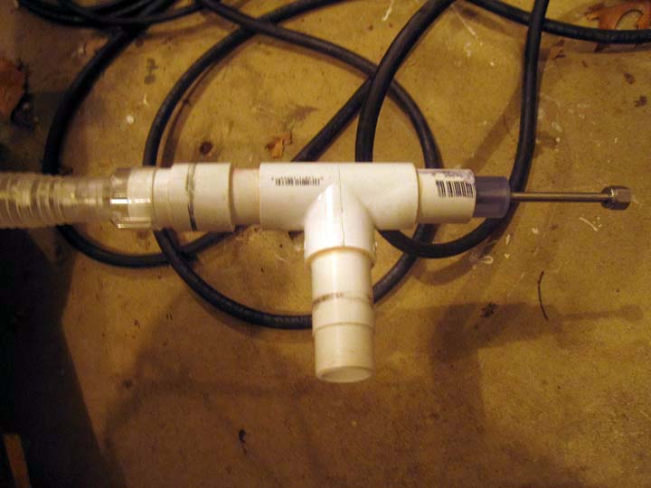
Pressurized gas enters the steel tubing on the right through a sealed orifice. Regenerated expanded gas enters on the left over the steel tubing. The gas exists from the PVC pipe back to the scrubber and compressor.
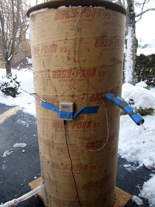
Outside view of tower. Warm gas enters the bottom tubing and flows up the tower. Cold expanded gas liquefies and is collected in a reservoir. The waste gas gets regenerated back into the system and flows out through the Teflon tubing and exits at the bottom.